Wednesday 23 January 2013

Research

Research is required to build any model correctly but we are all restricted by time and access to the information. This is true when you chose to build a model of something that did not exist in any substance and like all modelers an educated guess replaces hard data. Until the writing of the blog this is what had been done until a recent discussion with Ray Pilgram [Bylong]. Ray remembered a clinic that had was given on the Mary Vale to Golgong line at the Modelling the Railways in NSW Convention and that he would see if a copy of the presentation could be found. True to his word a PDF arrived via e-mail and the information forced a re think on the models design focus.

What was clear is that if the line had been build with the Golgong to Sandy Hollow line and the upgrade of the line from Sandy Hollow to Musslebrook the completed route would have become the main line of the system North to Newcastle especially for freight with it's superior grades. In the end what ultimately effected the decision was politics and the funding it attracted and that was the burden carried by the operators of the system. The NSWGR Railway's was not a business but a tool of its political masters.

This posed problem's for the layout design assumption'. The effect was to move the focus from Spicers Creek to Drill Creek and from Melba Road to Goombla with a 1925 starting point assuming the track up grade from Sandy Hollow was not completed. This allow's running the trains originally discussed and avoiding the need to run C38D57 and AD60 class locomotives which would be nearly impossible.

The article is reproduced and has been edited to focus on the Mary Vale to Golgong line:

Presentation for:
 Modeling the Railways of NSWGR Convention in 2003.

Sandy Hollow - Gulgong - Mary Vale
By Chris Wangmann

I would also like to say that a number of articles about the line have been produced over the years. I am in no way out to prove those articles to be incorrect, rather to say that this presentation is a result of my interest, research, inspections, operations and records.

HISTORY
The route of this line was originally surveyed in the 1855 to 1860 period. The Railway Surveyors are reported to have recommended that the main western line should follow approximately the same route as the Sandy Hollow to Mary Vale line from Newcastle for reasons of easier gradients over the Great Dividing Range. Political pressure of the day brought about the main western line being located where it is today. If it was constructed would provided a quicker route from Dubbo to Newcastle than could be achieved by traffic going via Werris Creek or Sydney.

The line then was initiated as a result of an investigation by a Royal Commission on decentralization of Rail Transport in 1911. It recommended a line be built from Mary Vale via Gulgong to Sandy Hollow, then to connect with the Muswellbrook to Merriwa branch line of the future. The Muswellbrook to Merriwa branch line was first passed by Act No: 11 of 1911. In1912 the first sod had been turned on the branch line and this was completed through to Denman on 25 May 1915. The Muswellbrook to Merriwa branch line opened fully on 29 October 1917. This would then connect the west of the state to a proposed new port to be built at Salamander Bay in Port. Stephens. The expenditure proposed for construction at Salamander Bay for shipping facilities, wharf lighting and dredging was to have been 600,000 pounds but was never constructed.  The Mary Vale via Gulgong to Sandy Hollow was to be constructed as part of this decentralization.

An advantage of the Sandy Hollow-Mary Vale line was to be gained by providing an alternative route to the coastal and western areas of the state and a quicker route-to the North Coast.  Although the proposed line would only be 122 miles shorter than the route from Dubbo to Newcastle via Sydney, it would have over 70 miles of easier gradients. The Sandy Hollow to Mary Vale line would provide the easiest crossing of the Blue Mountains from the West.  It  would  have 1:80 grades in the Up direction and 1:50 grades on the down  direction versus 1:30/40/44   on the main line from Dubbo to Sydney and Newcastle.  At this time the only route from the west to Newcastle was via Sydney.  The cross country line via Werriis Creek and Binna Way wasn't completed till April 1923.

According  to the Bulletin  magazine of the 1920's, which was a staunch critic of the Government, The Sandy Hollow to Mary Vale line would just be another  branch line off other unplayable lines. On the way to Mary Vale, the line would cross two other unplayable lines, they being Wallerawang to Gwabegar and Orange to Dubbo lines.

Proposed Mary Vale to Sandy Hollow line


The NSW Public Works Commission agreed to the construction of the Sandy Hollow to Mary  Vale line on the 7 January  1925. The length of the line would be 124 miles and cost around 1,172,895 pounds. On the 7 March 1927, assent was given to the Sandy Hollow to Mary Vale line via Gulgong Railway Act No: 28 of 1927. Land was acquired after the signing of the Act and before construction began. The plan for the Gulgong to Mary Vale section allowed for 5 stations and 1 tunnel.

Proposed Mary Vale to Gulgong line


The order from Golgong was:

Mebul Road, Goolma, Spicers Creek, Drill Creek and Comabella.  The name of the triangular junction is thought to be and has appeared in publications as Mary Vale Junction. The station at Gulgong was already in existence on the Wallerawang to Gwabegar line. 

* One tunnel would be required on the length of the line as well as 2 major bridges.
* The line was to be fenced fully and built for 60mph traffic,

* Gulgong was to have two triangles [wye] to allow traffic to flow to any direction out of the station.

Work did not start until approved as an unemployment relief scheme and on the 21st February 1936, State Cabinet decided to proceed with the construction of the Sandy Hollow to Mary Vale line.  The building costs permitted at this time were 1.353 million pounds but the actual expended to 1950 would be 2.43 million pounds. Construction commenced from Sandy Hollow heading West, Mary Vale heading East and Gulgong from both directions and involved about 500 men.

In 1936, the country as just coming out of the Great Depression and Europe was gaining a War footing.  The newly authorized line was expected to immediately run at a loss and that was not really wished for at that time.  The 1938 Annual Report of the Department of Railways stated the Muswellbrook to Sandy Hollow portion of the branch line should be strengthened to the same standards as the new line from Sandy Hollow to Mary Vale. The work between Muswellbrook    and Sandy Hollow was completed by 1950. The cause of the 12 year delay in upgrading  the Muswellbrook  to Sandy Hollow  portion of the  line would have  been attributed to the War and the fact that not much  was constructed between Sandy Hollow and Mary  Vale  during  the war years.

Work was steady  until  1939 when  World  War II broke  out and work was then confirmed to the tunnels  and 3 major  bridges,  mainly  due to a man  power  shortage. In 1941, the Commonwealth    Government   gave assistance in the form of 161,000   pounds to assist in early completion   of the project as a special incentive. During 1942 and due to the war, the Government drastically cut back on funding for the line. By January 1942, work was again stopped except for concreting some tunnels. During the war years of 1941-42, the Sandy Hollow to Mary Vale line, earthworks still-uncompleted, was once again raised in State Parliament with reference to its link to the Port of Newcastle.

In 1946, work  resumed  again but due to a shortage  of finances  and  steel,  some  bridges  were  not finished.  In 1949, the last equipment   was removed from the Sandy Hollow to Mary Vale project and taken to be used on the Branxton to Muswellbrook   duplication.   (Another railway project never finished)  Work  on the Sandy Hollow  to Mary  Vale line finally  ceased  around  about  1950, At this  stage,  85% of the  work had been completed. It was estimated  that on the  1st April  1964, the cost  to finish  the line would  be $16,040,000   (taken  from  a report  written  in 1967 and  expressed in decimal costs). At the end of 1965, although  no work  had been carried  out in 16 years, the work  completed included the following:

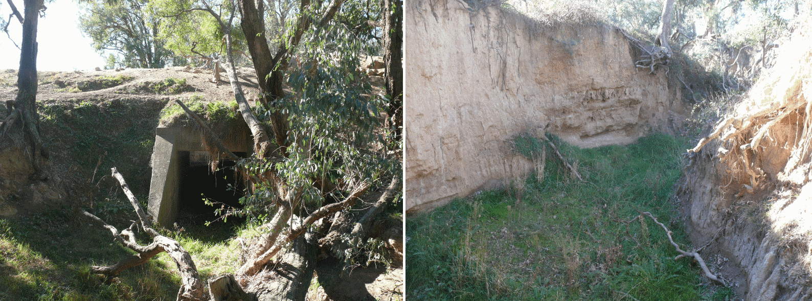
Some bridges are still there exactly as they were left during the 1950’s. e.g. Rush’s bridge (located on a property west of Beryl and owned by the Rush Family).

The platform faces and a goods loading bank at Comabella were completed and the platform at Gulgong was already in use.

Seventy five percent of the fencing along the line had been completed and all telegraph poles were in place.

Over culverts/flood openings varying in size from 2’x2’ to 10’x10’ had been completed also rabbit stops and cattle stops had been built. Road crossings had been formed and 95% of the right of way had been prepared.

In 1969, the Development Corporation of NSW decided that it should not be completed. After another lapse of 10 years or so, in 1980, the Government announced the Sandy Hollow to Ulan portion of the line would be built with an agreement with Ulan Coal Ltd and White Industries. The line from Sandy Hollow to Ulan coal mine opened on 15 October 1982.

The Premier Neville Wran announced that the portion of the line from Ulan to Gulgong would be built after the Sandy Hollow to Ulan line was constructed and this portion opened on 16 June 1985.


Location Diagrams and Data:


Drill Creek will be modeled with all the features shown with the Station being a PC2 with platform mounted levers : refer Drill Creek article for more details. 


Station will not be modeled : refer Spicers Creek  article for more details.

 
Goolma will be modeled with all the features shown with the station being a PC3 with a separate signal box : refer Goolma article for more details.

Conclusion's
We all have to thank other modelers who take the time to prepare these presentations and for preserving the information that they find - if you can go to a convention take the time to go and share with other modelers. 

Thank you Chris Wangmann.

For those seeking a personal cost of the actual construction follow the link to the Dubbo PhotoNews - click here

Saturday 19 January 2013

Track Sleepers

The series of videos on  The Route of The Arrow  on track work and specificity on painting sleepers [ties] and is a must view for those thinking of hand laying track. Visit OST Weathering Track Work web site as it will provide inspiration, incite and discussion on track work.

What will be covered here is the specifics techniques used to create the sleepers seen here.


After the adhesive has set all ties are sanded flat using 120 grit garnet paper glued to a flat piece of timber or Uni-Pro Sanding Block

Detailing is achieved in a time honoured manner by using a 42 tpi razor saw, X-Acto No 17 blade and dental pick. 

These detailing methods are covered in great detail in the OST - Detailing Track Work


After preparing all the timber sleepers the base colour of Mini-Wax Classic Grey is applied to all exposed timber faces. After the stain is fully dried weathering can commence. Mini-Wax Ebony is applied to all the heavily distressed areas. A small 1/8'' [3 mm] flat brush is used to apply the stain to these areas. The best technique is to just touch the area and allow the stain to spread. Continue to apply the stain outwards till the brush dry's out - reload brush and repeat. The goal is to taper the colour intensity. Some of the ties area's of plain ties can be blended with the Ebony Stain by loading a small amount of stain to the tip of the brush and then insert the bristles fully into methylated spirits [metho]  or isopropyl alcohol.


A alternative to using a liter tin of the Ebony Stain is to use Mini-Wax Wood Finish & Stain Repair pens are also available from Globak - click to go to web site

Once the stain is dried it is time to age the timber by applying Black Japan from Feast and Watson.

STOP here because this is were it can and will go wrong...!

Japan Black is an intense black and the fumes are issue and another suitable products could be substituted but it was used as it is a stain and is broken down by metho. Application MUST be done using a 1/8'' [3 mm] pointed brush. Dip the tip of the brush JUST into the Japan Black and  then into the metho bay about half its length. Just touch the tip into the deepest parts of the the distressing and allow it to spread - follow as the moment dictates and at the right moment insert the brush for full depth of the bristles back into the meto and flare the stain out. Try not to create stark blotch's or patterns but its just gut feel that will guide you.

When to you know when to stop?  The only advice that can be offered is when you begin to think "just a bit more" - STOP..!

In the example it may have gone to far and if it dose - stop - wait - come back and dry brush to break the effect down. The final appearance will appear a little stark but when the rails are installed onto the ties plates and it is in turn weathered it will break the effect down.


The final job is to remove all the fur from the sleepers. I use 180 grit Uni-Pro Flexible Sanding Pads.  They are flexible and conforms to the sleepers and remove most of the fur in one swipe. The other effect is to fade down the sleepers a tad and at this point a thinned mix of Classic Grey can be added using a large brush in a semi dry brush techniques. Tamyia Sky Grey can be dry brushed to further age the sleepers or break down some of the Japan Black.


Monday 14 January 2013

NSWGR PC 2 Station

Brief Concrete Building History.
The concrete building of the NSWGR was an outcome of the need to reduce maintenance of the timber-based designs. The first designs were placed in service in 1917 but came to predominance in the 1920s. Over the years the design was refined but the major difference was that till the mid-'20s the slab was based on a 15'' design. After that time the design was changed to 10'' with other improvements to reduce leakage and improve appearance. The designs were modular giving great flexibility in layout but all shared the same base dimensions and floor layout.

The majority of these buildings were placed on freight lines which makes them correct for the Gulgong to Mary Vale line. The designs were given the prefix of PC with PC 1 begin the most basic design functioning as a shelter, waiting room and goods store. The PC 2 had accommodation for station staff both for work and overnight, making the design perfect for Spicers Creek. For those requiring more information, a good article can be found in the Australian Journal of Model Railway Modelling - Issue 7 and at the time of writing back issues were available. The renders are for the final design that was developed using a HO kit version from Rail Central, Issue 7 of the Journal and Greg Edward's Data Sheet No B 27.  

Model Construction. 
It was decided to develop a 3D solid model's of the PC 2 station and have the necessary components manufactured as high-resolution rapid prototypes. The final models will be cast in urethane, assembled and offered painted and assembled in three parts foundations, building and accessories. ModelFxs is currently investigating assembly by a third party so this will be long term and no information will be available until the models are ready for sale due to the unknowns involved.  The era of kits is really over for the time begin as most modellers are as a group time-poor...!


Renders of the models are shown below:

Click for a video of finished product


The colours shown are not prototype and have been used for clarity when rendering only.


Sunday 13 January 2013

Couplers & Buffers

Upon entering the world of 7 mm NSWGR the first question asked was  - " What standard are used for couplers and buffer heights? "  

The answer was at this time none are defined but check the prototype...! 

So after examination of all the kits in stock the Waratah S truck would be the worst to modify the coupler pocket but was close to prototype standards. This was chosen as the basis of the standard to be applied to this project.

Construction of a Waratah RU - Bergs LCH - Aust-O BCH proved that all need some or a lot of modification to match the "S Wagon Standard " but it stood the test.


With the problems of buffer height and coupler centres resolved selection of a coupler was the next consideration. After reviewing the current lost wax couplers and the Kadee none met the necessary criteria of operation or appearance.

Wagons coupled


It was decided to use an undersized couplers from San Juan Car Company for a number of reasons. Firstly they can be made to operate with a HO Rix magnetic un-coupler thought this is a work in progress. Secondly the head size was more acceptable and the trip pins [air hoses] are not as low as the Kadee placing them in a more prototypical location.
 
These couplers have some special requirements for mounting and the plastic whiskers are a concern as they are not a proven solution and will be reported on here much later..!

Couplers and Buffer Lock.

This was a common problem in the operation of NSWGR O scale wagons and justified an effort to define a suitable settings for this project.

It was decided that a fixed relationship on the rolling stock would be required for the buffers and couplers with a minimum operating radius. The datum for both is the buffer mounting face on any piece of rolling stock.

  • Buffer length - 9.5 mm tolerance + 0.1 / - 0.2 mm overall. 
  • Coupler to inside face knuckle 10.0 mm tolerance +0.25 / - 0.0 mm or 11.75mm to the face San Juan coupler
  • Minimum radius 1650 mm


    BUFFER OVERALL -FACE TO MOUNT

    NOTE - 22.2 SHOULD BE FROM TOP OF RAIL


    COUPLER  LOCATION

This allows coupling on a 1650 mm radius curve [minimum] and the cars to operate correctly with no apparent buffer or coupler lock when fitted in the standard manufacturer coupler boxes.


Four wheel wagons on 1650 radius curved point


The standard developed may have to adjusted but so far it has allowed the equipment to work correctly and will be continued to be used as described unless a unforeseen problem is encountered. 


If fine tuning or scraping is required in the future it will be noted on this page...!.

Wednesday 9 January 2013

Sound Control

When adding sound to any model the biggest problem is the repetitive nature of the sound created using recorded sound and the access to flexible control. Recorded sounds  repeated during a operating secession will allow operators to learn the sound patterns and creates a audible “three step” dance in the listener mind.

The type of sounds will effect how quickly this develops but the more distinctive the quicker it will occur. Background environmental sound are harder to learn like a wind sound but add a thunder clap and a pattern is quickly created. The rate that these sounds are detected are generally a function of  the uniqueness of the sound and volume not time. The worst type of sound is the human voice at any volume as we are trained to detect speech quickly. 

Can a three step be avoided? The short answer is no as perceived sound in the real world world is a combination of a series of point sounds that are mixed in our heads via the ears. In real terms sound is so dynamic that there is no way that we can replicate it but it can be simulated and if done carefully the listener can be fooled - its done on theater stages every day.

Power & Control

Power to each module will be supplied by a NCE DB3 Booster that produce 3 amps continuous power. This booster will be used to provide all power to run all the accessory bus hardware in that module. All devices will be connected to bus using a suitable stationary decoder. This allows all elements sound, building light and points to be treated as a digital address allowing all items to be controlled by any device that will connect to the DCC control bus. This allows effects such as lights, smoke generators and animations controlled by a accessory decoder and to coordinate them with sounds.

A final advantage is that power is available immediately for such items as lighting as the decoders supply of 12VDC.

  
Stage Set Sound Control - Philosophy

The will use a laptop running JMRI to communicate using the NMRA DCC accessory bus to provide the control platform required. 

JMRI running a time based script provides a major control element allowing any NMRA DCC accessory address to be turned on and off.  The scrip can be easily edited and a number of scripts developed that when used over any time would help randomize the specific point sound's so that any operator will not be able to predict a sequence or "three step"

The control of the specific point sound [Foley] is of course not just a time based element it is also a action based so this creates three distinct group's of sounds requiring a different control approach. The three type's of control can be loosely described as scripts as just discussed, operator action based and location based sounds.

This will be best explained by example:

Script Based Sound: Typical sounds are birds, insects and generally these can be grouped as environmental based point sounds that have nothing to do with man or his equipment at any given location. This is why a script is required to randomized specific sounds.

These sound will  require a background to be built on and a winds based theme has proven to provide such a platform. The wind file is just plain wind with the normal fluctuations but no specific sounds. A separate file can be produced to included a thunder storm for that occasional special event.


The  Pricom Dream player is the ideal tool to support this type of background track as it provides a solid state player that loops and provides four [4] separate tracks that can be selected using a stationary decoder.


Operator Based Sound: This group of sounds are based on a operator or human intervention into the environment. In our case the operation of a lever frame will create the sound of the lever and associated hardware all the way to the slap of a point. It can also be off railroad action like the sound of cattle or sheep being loaded onto or off cars in a siding and the list is limited only on the features of the layout as installed in the stage set.

Both examples have a subtle difference's as one will be operator equipment based and the other action based but both will require the operator to trigger the sound using a digitial or analogue interface on a facia

In the case of the lever and points these sounds are attached the the operation of any specific point or lever and use a DCC address to tie the sounds to the equipment. The cattle and sheep will require a push button to be placed near the unload point requiring an operator to push the button to trigger the sound associated with that action.

Location Based Sound: These sounds are created by the presence of locomotives in there operation on the railroad and examples of these are bridge rumble, flange ring etc. and  are triggered by suitable detectors located in the structure or line-side.

Flange ring is a good example of this type of sound and dose add to any railroad as it makes a strong statement and is quickly associated with movement and mass. The activation of these sound are equipment based only and requires a distinct approach.  This involves placing the player into continuous mode and the connecting the detector output to a relay with one of the speaker wires run through the normally open contact. When the locomotive trips the detector the contact closes and the sound starts and will hold while equipment is closing the detector to provide sound on demand. Bridge rumble is another sound can also be included in this category.

Foley Sound Creation

The point or foley sounds require a special type of player some are already on the market but lack flexibility and are difficult to trigger using accessory decoders. ModelFxs has created two new products to meet this specific need.

The ModelFxs Sound-Byte Sound Player allows two prerecorded modules to be fitted each storing 45 seconds of point or foley sound. This unit is fitted with a integrated NMRA compatible DCC decoder allowing single or loop playing of each specific sound and supports 4 sets of distinct address and can trigger a almost unlimited number of player using the MFx control bus integrated into each player. Each sound has it own 1 watt amplifier also integrated into the board to allow more that adequate sound control.


Sound-Byte Player pre production sample


The ModelFxs Sound-Slave  is the stand alone player that takes a single pre-recorded chip and also has a intergrated 1 watt amplifier and a MFx bus. The MFx bus as the name sudjest allow it to be slaved to a digitial address.


Sound Slave pre-poduction sample

The final item that set these apart is that the sound modules [Sound-Blocks] are user recordable using a ModelFXs Sound-Recorder and will capture any sound that can be heard in a device earpeice.

These are due for release soon - end of add for ModelFXs.

Conclusion
Now a very dynamic and flexible environment exists that can as much as possible avoid the “three step” because the mix of sound will be different every time a locomotive is driven onto the stage or when a operator has to preform an action or just because the script has triggered a sound.

What is acheived by this arrangement is that a sound track is created not compiled so it is totaly dynamic and created on the fly and in truth never the same at any given time. The fact is a operator assembles the sounds in his head as in the real world.

Saturday 5 January 2013

Spicers Creek

As discussed in the Philosophy Blog this model can be defined as prototype freelanced.. Fortunately or not defined infrastructure was constructed at Spicers Creek and as this is the first of the modules it is appropriate to examine what exist and its effect on the stage sets design.


Area and features to be modeled


The original line was a proposal attached to the construction of the Denman line which if all the infrastructure had been constructed would have made Sandy Hollow to Denman a branch line with the Sandy Hollow - Guglong - Mary Vale a secondary main at least across the heart of the state. The key to the final construction of the Sandy Hollow branch was the existence of coal and today is the reason for the line's continued existence.

The area of Spicers Creek is currently rich in farming mainly cattle and sheep so this will be used to create additional traffic on the line. The development of a history is part of of the philosophy that  develops constrains for the model to operate in. The integration of the existing infrastructure defines the infrastructure that will be modeled, trackage layout and scenery used in a individual stage set.


Bridge Pylon Maryvale side Goomla Road


Bridge Pylon Gulgong side Goomla Road

These bridge pylons are a must model feature for the Spicers Creek stage set as they a located on Goomla Road and will anchor the model into the real world. The bridge will be a 24 foot deck girder bridge from Waratah Models.


Drainage near bridge abutments

Examination of the existing infrastructure shows that drainage culverts were spaced about every 500 meters along all the embankments which have stood the test of time and for this reason and are a must model feature. The one shown are located just after the pylons and are a must have.


Embankment Mary Vale side

This photo shows a grove of trees in the distance that cross a small creek. This will be handy to disguise the set entry along with the rows populars along the road side near  pylon. These are located on the aisle side on the model and should form a nice view block thought a lot of selective compression will have to be applied.


Embankment Gulgong side


Right of way Gulgong side

These two shots were taken looking back from the pylon to Gulgong. The area is accessed from the Cemetery Road.. 

Points of interest at Spicers Creek


Church Gulgong side

The church history is unknown but if room is available would provide another anchor for the model set. The old cemetery would be an ideal model as it appears to be a pioneer site. Access is not available as it is now on fenced land but is a definite must model as it is so small.

Details of the general cemetery can be found in this link - click here

Cemetery Gulgong side
Stage Set after field research. 

Spicers Creek station would have been located about 1 km up the line from the bridge on the Mary Vale side based on the research information prepared by Chris Wangmann.  Model railways modelers tend to want to fill all scenes with as much infrastructure as possible for switching and other reasons but this dose not allow operators to get a sense of travel if moving from one station to another.

Sometimes less can be more..!

After examining Chris Wangmann article and the track diagrams for Spicers Creek it would featured a passing siding with cattle yard. Drill Creek is a major station so the Spicers Creek would be a running stage set built around the existing bridge abutment's to create that sense of distance when traveling between Drill Creek  and Goomla.


To view in larger format - double click - then select image

Creek Crossing
Studying the tree line along the creek line seen from the Mary vale side of the abutments it was envisioned that 3 span deck girder bridge of a total length 72 foot would be incorporated in the model. 


The image of what the modeler wanted to see [Chris Wangman photo]

On the second trip to measure the abutments for modeling and knowing the way to the creek side it was decided to try and photograph area. After carefully scaling barbed wire farm fences the reality did not meet the mental picture.

Instead of seeing a wide slow moving creek I was confronted with a dry creek bed and a large single concrete culvert - the mental picture popped! It was a salient lesson in how our ideas are always grander than the simplicity of the prototype. 


The reality behind the tree line
A quick walk through the culvert to the other side revealed the damage that this design approach created over time, proof of its inadequate nature. The culvert outlet has cut a vertical canyon a 10 - 12 meters deep with the outlet of the culvert eroded away creating a vertical drop of 3 meters at the exit undercutting the culvert floor. The damage is clearly the result of a single culvert with a huge load of water created by the embankment with a single outlet through the culvert equals huge water velocity at the outlet with the spectacular erosion created. 


Culvert at entry                                                                   Culvert at Exit

The question is how to model the scene as the mind saw it or the cold reality. What is in no doubt is that if the line was constructed at least two more culverts would have been added to reduce water velocity but would they have been concrete - tubular metal culverts or maybe the illusion is just better modeling....! 

The photo above of the girder bridge located near Mebul Road and is what the modeler mind created for the crossing - now maybe if the piers are a little lower...!

18/1/13 - Page revised in light of new information received on the line
16/6/13 - Culvert chapters added