Currently no commercial nickle silver lost wax castings are available to aid in the construction of a NSWGR turnout. After examining available suppliers Right-O'-Way was selected. Lou Cross the owner does not have a website and has to be contacted at (559) 665-1001 [USA California time].
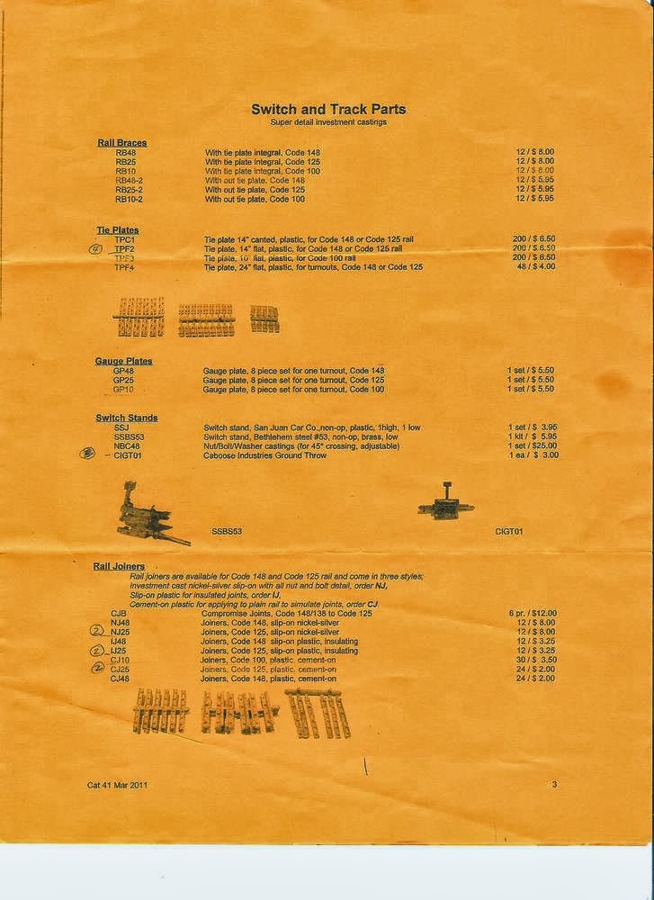
Refer to article on Right-O-Way for the catalogues on the parts used.
The castings offered by Right-O-Way are modified or adapted to produce a reasonable representation of a NSWGR turnout while offering the leverage of begin commercially available. The series of videos on The Route of The Arrow on track work are a must view for those thinking of hand laying track. What will be covered here is the specifics of how to create a NSWGR turnout using those available commercial castings.
The best reference on track work and associated infrastructure is the Greg Edwards Trackwork Manual. This will provide the a initial guide to assembly but nothing will match field research as it quite apparent that design features are quite flexible in the field.
You will need is a code 125 #6 or #7 bolted frog, guard rail and 18'-0" blade's, code 125 tie plates, 6 bolt fish plates and cast rail joiners in nickel silver and plastic as required. The rail joiners feature bolt detail and are a slip on design.
A NSWGR turnout will require a jig to allow efficient production of the correct sleeper lengths and alignment. The jig shown below is available from the Aust7 Modellers Group Inc.
The sleepers to suit the jig are produced by Kappler [KPOOSL-O_BULK 4" x 9"] and require four [4] of the 600 mm lengths per turnout are required, cut to length and then insert into the jig. For this operation the jig should be on a flat surface orientated for a left hand or right hand turnout. Once all the sleepers are finished all the sleepers are tied together using two [2] strips Midwest 1/8" x 3/4" basswood. This is fixed to the underside of the sleepers using acrylic sealant by applying a dob of adhesive at each tie - there is adequate time to finish before the adhesive sets. Fit the 3//4'' basswood strip 26 mm inside edge to inside edge about the center line of the turnout. A separate piece is added to tie the area under the curved rails - refer photo for details.
Note: The 1/8" basswood strip will match the sleeper mount produced by the Aust 7 Modellers Group and aids assembly by allowing guide pins to be used to locate the straight stock rail as a reference for all the other components.
After the adhesive has set all ties are sanded flat using 180 grit garnet paper glued to a flat piece of timber. Detailing is achieved in a time honoured manner by using a 42 tpi razor saw, X-Acto No 17 blade and dental pick. These detailing methods are covered in great detail in the OST Publications on track mentioned in a previous article and detail in the Weathering Sleepers article.
Once complete stain the ties using the "Classic Grey" MinWax stain. This procedure is outlined in full detail on the The Route of The Arrow article so it will not be covered here.
Side Chair & Stock Rail Assembly
Side chairs are manufactured by Waratah Models and 2 set per point were required for this assembly : 2 short plates and 9 long are used per side to suit the 18'-0'' blade from Right-O-Way. Dress the casting before assembly paying attention to the thickness of the base and ensuring that all are about equal in height.. Clean the undercut on the chair were the flange engages at the base with a razor saw. This will allow the chair to better fit the rail when installed.
Right-O-Way code 125 steel rail was chosen for that final touch of realism.
Cut a two lengths of Code 125 rail to the overall length of 560 mm. Clean the underside were the chairs are located lightly then coat with paste flux and tin with rosin core solder - dress smooth with a flat single cut bastard file. Remove the side chairs from their sprues and dress them on both faces. Drill 0.025" thought on the centres provided. A length of rail is laid perpendicular to the ties of the jig : two weights are laid on the top side to apply pressure for assembly. The chair jig is a piece of cardboard with the tie position traced from the tie jig.
The weights are used to hold the parts in place for soldering with the chairs about the centre of the traced tie's.
Fit the long chairs at each end using the two thickest for this job, solder and fit side chairs under the rail at every second tie - aligned the chair and sleeper then solder from the inside [flat] face of the chair using a 0.5 mm rosin core solder. Repeat at each point then insert the missing chairs and repeat till all openings are filled. Finally install the short side chairs at the entry to the blade. Dress the top side of the chairs with a flat file to ensure the full length is flat then repeat on the underside. Do not break through the tinned face as this will show brass - re tin if required.
Repeat for the other side remembering it is a mirror image of the first assembly.
Clean the finished assembly with wax and grease remover and remove all excess flux.
Notch both ends of the rail to allow the installation of the code 125 rail joiner lost wax casting. The notch allows a tight prototypical gap or the gap can be filled with solder and dressed to profile.
To prepare a notch file a 2 - 3 mm wide cut from the base or the rail to the underside of the rail head and then file head to about 0.75 mm [0.030''] thick. Fit the rail joiner and adjust to fit correctly : apply flux then refit rail joiner with its centre aligned with the end of the rail, solder from the underside through the gap on the underside of the rail joiner.
Clean assembly of all flux and wipe with wax and grease remover. Mark the centre line of the length of rail then apply the plastic code 125 rail joiner castings on both sides. This should be 280 mm or 40 scale feet. If four [4] bolt plates are required trim before application.
At this point fully prime both the rail assembles all round with White Knight Etch Grey Primer available from Bunnings.
Casting Preparation
Guard Rails [part #GR25]
To produce the long guard rails use two 11'-0'' guardrail castings to produce a 15'-0'' guardrail. Cut as per the photo below then solder into a one piece assembly. Only apply paste flux to the inside face and joint face to reduce excess solder moving to the front and once soldered dress with a fine file.
Modify the rail spacers at both ends by cutting the excess using a razor saw and file into alignment. If you have access to a ridged disc sander this is much quicker. File the under side of the spacer using a flat file with a safety edge to re-create the under cut to clear the rail web and modify till correct fit to the rail is archived
You can also use the casting as supplied as a 11'-0'' guard rail, square the ends and if you want to match the data sheets remove the crank with flat pliers and adjust to the data sheets. Dress the spacers as noted above.
Turnout Blades [part #P25-18]
At this time there are no turnouts blades are available without the side reinforcing bars so the Right-O-Way blades will have to be modified by filing off the rivets on both sides by using a modified points file.
Grind to 2.5 mm wide and square the end to create a scraper.
A 3 mm square square file is use to remove the bolt heads then the scraper is used to remove most traces of the rivets and to achieve a smoother finish. When complete clean the profile of the blade were it engages into the web - check on a scrap piece of rail and adjust until it engages flush at its tip into the rail web.
Drill through the pivots for the blade using a 0.2 mm [0.02''] drill trying to intersect with the small boss on the underside of the clip. When drilled file off the top boss's to allow installation of the throw bars pivot pins.
Install the blade in position on the sleeper chairs and check fit, straightness and twist - adjust till correct. This is important for correct operation of the turnout and it is nearly impossible to correct properly when fully assembled.
Note: NSWGR blades are shown in Greg Edwards Data Sheets as 16'-6'' and Right-O-Way do have these in stock and can be used as described. The reason the longer blade was used is two fold. First it appears to fit better in the jig assembly when 9 of the long chairs are installed as shown on the data sheets.
Secondly the blade is soldered after the 9th chair to the brass plate and there was concern about the need of the blade to flex as it can not hinge at that point. The reason for soldering the blade was to provide a 100% reliable connection to the stock rails that carry the feeder tabs. Will the shorter blade work at the time it was decided to be play safe. The final selection is up to the reader and their personal preference.
Rail Joiners - Metal [part #NJ25]
The rail joiner needs to be cleaned up on the inside face. Use a piece of brass 0.013'' thick and 120 or 180 grit wet and dry. File the inside carefully till they side onto the rail. It will also be necessary to dress the top and bottom of the casting as required.
Tip: Fold the wet and dry paper around a strip of old etch fret.
To ensure the smoothest possible operation it is recommended that the flange located at the top of the casting above the bolts be filed down. It operation it has been found to catch a wheel flange depending on how well the casting is fitted to the rail, This is only necessary on the running face of the casting but must be done if running NMRA standard wheel sets.
Painting
Prime all the castings all round with White Knight Etch Primer Grey primer.
Spray or brush paint all the components including the rail and tie plates. The colour is a mixture of Tamyia Red/Brown and Orange in about a 50/40 mix with less of the orange for variation. This was done before before assembly to obtain a neater job leaving only a touch up after final assembly. Do not paint were soldering is required as the primer will burn off with the flux if sprayed lightly.
 |
Turnout Terminology
|
Turnout Assembly
Straight Stock Rail - Step 1
Begin by laying the jig over the ties and using the point marked B for code 125 rail and if using code 100 use the point marked A . Push the Peco pins through to fully engage into the 1/8" x 3/4" bass wood strips at each point on the jig and then cut the head off with a old Xuron track cutter allowing removal of the plastic jig.

Place the rail web against the pins and insert Peco track pins thru the short chairs located on the sleepers at the entry to the turnout. On the first long sleeper chair pin both of the outer and one point on the inner using the hole closest to the throw bar then repeat at the far tie at the frog end. Once happy with alignment pin all the sleepers chairs on the straight rail.
 |
| Connector |
The first tie plate is manufactured from brass strip sized 4.5 x 11 x 0.4 mm thick. The ones in the photo were laminated from two layers of brass fret, drilled 0.025'' at the correct corners and spiked into position.
Flux before assembly.
This plate provides a fixed location for the rail but is the path for providing a positive electrical connection to the blade which is soldered to it after installation.
Tip: Peco track pins will need to be selected by head size as some are quite large and the smaller ones give a superior result. I bag the others to use as track spikes later but please note the Micro Engineering No 30106 small spikes are more typically used and are a cheaper option.
The first tie plate after the brass plate will need a 0.010'' x 0.156'' packer glued to the underside - dress to fit. Installing the tie plates with the long side of the casting placed to the outside edge and spike the ties in a staggered pattern consistent with the direction the turnout will face on the layout.
This rail is now the fixed reference for all future assembly.
 |
| Roller Gauges Aust 7 |
Frog Installation - Step 2
Select a Right-O-Way #6 frog [part #FB25-6] or #7 [parts FB25-7] The back to back spacing of the rail head is 32 mm to adjust your gauges before starting to lay any track - recheck before starting final spiking. I used a cardboard gauge as seen in the photo. This was used for initial assembly as discussed below but the metal gauges must be used when spiking starts.
Note: To use a #7 frog with a #6 tie assembly a little fudge required..!
Recommend: Solder a strip of 3 mm x 30 mm x 0.25mm brass strip onto the underside as the frog feeder.
Tip: Cut from a strip of old etch fret
Drill a 0.5 mm [.02"] hole thru the spreader centres at the entry and counter sink with a 0.04'' [1.0 mm] to full diameter. Locate the #7 frog on the sleeper assembly by positioning the block against the face of tie 38 [refer location on jig] and once spaced at 32 mm from the reference rail insert a Peco track pin through the previously drilled hole into the sleeper - this must be nearly flush as the wheel flange will pick it up in operation.
Locate the frog by placing a series of pins at the edges as require to locate the frog. Check the position from both ends of the frog which must be 32 mm from the inside of the straight stock rail head.
Insulated Joiners: If you chose to use the Right-O-Way insulated joiners it will be necessary to notch the entry and exit of the frog to clear the spacer on the insulated joiner.
An alternative method is to use plain rail joiners and glue paper insulators into a gap cut with a razor saw at the joint of the rail and the frog casting. To do this ensure that the point rails are butted hard against the frog during assembly. Using a piece of plain bond paper coat both sides with ACC and allow to dry. Recoat and insert into the gap, allow to dry then dress the frog as required.
Note: This is the preferred method of adding insulated joiners as required in any track work.


Spike the frog into position using Right-O-Way TFF-4 extended tie plates under each sleeper. Position the tie plates and use the single hole to spike the plate into position. For this job I used Peco track pins with a smaller head, this will require a search through the packet.
Comment: When nickel silver casting were refined by polishing the brass base begun to cast a gold hue to surface, While this is not a problem on the blades it was highly noticeable on the frog due the the area presented to the viewer.
On the turnout as constructed the areas where electrical contact is required were carefully painted using silver conducting paint used in PCB repair. This paint should not affect pickup and will in time wear away which may or may not required touch up. It is recommended that the area not to be silver be masked using Tamyia 6 mm wide tape cut to profile and painted rust as a final operation. This operation may be undertaken as one of the last steps.
Final comments will be added after operating the modules,,,!
Setting Curved Stock Rail - Step 3
Bend to a nominal 3 - 5 degree set just after the second small sleeper chair in the direction of the curve. This is necessary to allow installation of the blade and to achieve the necessary clearances.
Lay the curved stock rail in position and pin 32 mm from the frog and at the the long ties. This will allow the curve to be developed - pins and adjust as required. At this point it MUST be free to allow final adjustment to the curved point rail after its installation.
Repeat at the exit point of the frog. In the photo exit rails have been added for final adjustment of the curved exit. It is critical that the curved stock rail be gauged at 32mm from the frog. The exit rails were added as a final check of the general fit and alignment for the location chosen for the #7 frog on the prototype. Were conflicts exist with the two photos above follow the text.
Curved Point Rail- Step 4
The point rail are manufactured from the stock rail off cuts. Notch one end to fit a the turnout blade - locate correctly but do not solder. Using fingers to curve the point rail to match the radius of the curved stock rail pinned to the sleeper assembly. Pay particular attention to achieving a smooth blend or tangency with the frog toe or entry.
Fit a Right-O-Way blade onto the rail, gap and solder to stock rail. Check fit of blade in place as re-adjust to achieve a good fit. Place the point blade in it final location against and lay the rail up to the frog - mark the rail and cut to length - dress to fit and notch end to fit a insulated plastic joiner. Refit assembly into location and adjust till correctly located then remove and solder the blade, ACC the insulated joiner and reinstall for spiking.
Ensure that the curve point rail is a smooth blend into the frog and generally follows the curved stock rail. Once satisfied begin fitting the tie plates under the rail. Place a 1.5 mm [0.065"] spacer along the full length of the blade, when fitted solder the rail to the last side chair located just after the rail joiner. This provides an anchor point for the blade and is soldered to create electrical conductivity and structural rigidity.
The first tie plate after the brass plate needs a 0.010'' x 0.156'' packer glued to the underside. Do not fully spike the last two till the first batch of tie plates is fitted. Repeat till you reach the the frog always checking that you are creating a smooth curve following the line of the curved stock rail.
Tip: Place about 6 tie plates at a time long side out and spike up to the last two as it can become tight to begin installing the next set.
Fit the rail gauges and repeat for the curved stock rail remembering the long tie plates are required under the guard rail and exit at the hinge, keep checking all the time to maintain the 32 B/B gauge.
Remove the packer and test with a spare truck or wagon. The car should run smoothly thru the completed assembly.Check operation of the blade it should mate with the stock rail with no gaps or misalignment - if there are any issues do not proceed till rectified.
Straight Stock Rail - Step 5
Repeat the operation outline above for the curved stock rail. Particular attention should be taken with the straight point rail alignment into the frog - it may be necessary to tweak the frog casting to achieve correct alignment from the blade and the frog.
Throw Bar - Step 6
The throw bars are Right-O-Way lost wax casting and require final assembly. Comprehensive notes are provided and should be read. Right-O-Way recommend the spacing between the pivots of 0.9'' on the points but as constructed 0.95" was used for appearance and to allow the blade to not foul the pins on the sleeper chair castings which are a tight when installed.
Relieve the flat casting with out the clamp detail to about 70% of the total thickness for about 3 mm the check fit into the mating casting. When correct use a piece of the header supplied with the bag and file across one side using a fine points file. This thins down the paper and allows it to be use as the insulator as described in the Right-O-Way notes. The super glue impregnates the paper and creates a laminating paper that is strong and insulates the two bars.
Fit the throw bar to the main pivots and pin with a Peco track pins - check operation - trim pins to project about 6 mm and apply a slight bend to captivate.
Prepare the second throw as per the first but remove the throw attachment on the side with Xuron Track Cutters, dress and prepare as per the main pivot BUT do not assemble. Re-install 0.06'' [1.5mm] packer along straight stock rail and pin as described above then swing together - check operation - split and apply ACC and reassemble - ensure assembly is straight with a flat pair of pliers.
The throw bar attachment is a length of CMA 0.03'' phosphor bronze wire soldered into the hole provided in the casting - check fit before assembly.
Note: The wire MUST exit on the same side as it is attached failure to do this will create a dead short that is hard to find later. If you are not sure which side that the throw bar is to be fitted wait until installation then determine the side, remove a piece of 3/4" strip at the throw bar and ACC 0.010'' styrene for the full length of the underside of the rail if a short is to be created. older the CMA 0.03'' wire using Burnell Hobbies 188 deg low temp solder as the ACC is very sensitive to heat.
Check Rails - Step 7
Install the check rails by referring to photos or Greg Edwards Track work book. The TF4 long tie plates should be in place so locate the check rail for fit. When ready apply 3 drops of ACC to check rail to the tie plates and fully spike.
When complete simulate the bolt heads using Titchy 1 5/8'' nut castings [part #8144] bolt and washer casting. Mark locations of the bolts on the outside of the rail with a 0.5 mm pencil.
To apply cut each bolt and washer behind the washer - pick up with a fine needle and dab the base of the washer into a small pool of ACC. Using the needle place of the face of the web - spin the needle to release the casting.
Weathering - Step 8 [Optional]
The side rails were finally weathered with dark brown weathered chalk from Bragdon Enterprises or in Australia the MRRC. It will break down the stark rust of the paint. These chalks are bended with a dry adhesive that aids adhesion to the rail.
The chalk is applied in small clusters along the side of the rail and then scrubbed into the side of the rail using a 8 mm wide short hair brush. Highlights of the rust can also be added and finally the grease stains on the moving parts.
Tip: Purchase a cheap flat 8mm paint brush and using a Xuron rail cutter trim off about 30 - 40% of the brush. It creates an ideal scrubbing brush for this job
Final weathering will be done after installation and ballasting.
Wiring - Step 9
Regardless if you use DC or DCC these points MUST be constructed DCC friendly, this means the left hand side is insulated from the right hand side and the frog is isolated.
Cut the basswood strip to allow access to the underside of the point to fit the 3 x 30 brass strips This job can be done at any time but it is recommended the brass tabs be added to the stock rails before installation. Continuity to through point rail and blade is provided when the respective assembly's are soldered to the brass plate outlined in step 1.
Check that there is NO continuity with the left and right hand side of the turnout assembly and that the frog is isolated from the left and right hand rail using a the buzzer on the multi-meter.
Feeder wires are attached to the brass tabs and the frog will require that power be routed from the left or right rail as required. The brass tab are bent at 90 degrees at installation to the layout.
Finished - Step 10


 .
.


