Showing posts with label Infrastructure. Show all posts

Saturday, 4 September 2021

Rabbit Trap - The Model


The prototype was measured on a field trip and a 3D model was produced shown in the rendering above. There use is discussed in detail in a previous article on Rabbit Traps. The model was rapid prototypical and cast in urethane by Peter Boorman Models in Queensland. The urethane castings where assembled into the completed model shown then painted in weathered concrete, washed to age of 30 years. One complete assembly is fitted at each side of the embankment.

No information can be found at this time on the beams that supported the rail except that they were mostly likely steel. The problem is how was the rail fixed and at this point a educated guess is applied in the form of clamps. This form of construction would allow the beams to be completely fabricated off site, fit to any rail and allow replacement of worn sections, so for now this is how it is modeled until better information becomes available.


The pit is 66 mm wide


Thursday, 2 September 2021

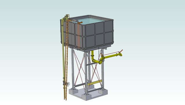
10000 Gallon Water tank

Decided to finish the 20000-gallon water tank that was on the PC for a number of years. This took a lot more time than you would expect. The primary reason was that the original software that I had used was dropped by AutoDesk and I could not afford the upgrade to Inventor. There was a problem with the 40 Class kits and I had to address that in between the other major project that I have.

That was a long exercise as no one in Australia could do it and I finally found someone located in Russia and engaged him to salvage as much as he could. Finally decided on Albire Professional 3D Software or what I call Solidworks Light, getting a licence for a heavy discount for marketing reasons helped, still $650 a year but it works well and has excellent constraining for assemblies.

The files were finally rescued and sent back in SAT format and at least they could be loaded. The final issue was that it took me 3 plus months to even get my mind in the right place with the software

This is the backstory, but I missed the tank assembly had some parts but not the tank.

After a lot of work, a new tank was generated for the 20000 gallons and finished this is where someone showed a picture of a 10000 gallon and yes it looked better, back to the grind and this is the final result. It is not a museum piece just layout quality like the PC2 Station which can be handled and still have one part at the end of the day.  It has no prototype just a collection of parts with the arrangement based on general structural knowledge and what is available.

Most of the major parts will be 3D printed with the frame Evergreen Styrene. The spout may be either plastic or brass castings depending on success with the latter.

The images are of the model, not a scale drawing so all sizes are of the materials used and the compromises made for the manufacture of one-offs.


10000 gallon Tank with Spout Generic

Details are shown below


Wednesday, 16 October 2013

Power Poles

The NSWGR recycled old rail for fences and power poles along the full length of its right of way. Ray Pilgram provided a series of photographs showing a series of line side power poles in various locations and while all are of a similar construction but there are too many variants to cover in this article.


Pole Construction


Prototype

3D Solid Model Rendered Image 

The image for the cross arms was extracted from a Ray Pilgrim photograph taken at Werris Creek and clearly shows the arm construction allowing the 3D model to be created and the parts sent out for rapid prototyping. The model is about 25% oversize to allow the detail to be reproduced and to allow urethane casting. A separate photo of the Silver City Comet taken in the 80's out west provided a template for the poles.  

Technical Notes
Ray Pilgram on his Bylong Blog has posted some PDFs on the technical detail related to the installation of telephone poles on NSW Railways plus some additional notes of interest

The main document "Line Route Maintenance & Construction" has all the relevant details for those seeking to construct the rail based poles. There are another series of manuals for wooden construction on the same site for those seeking an alternative to rail. 

Cheat Notes:
The relevant points for modelling are listed below

Minimum rail length 30 feet [9 meters]

Spacing 165 feet [50 meters]

Standard cross arms are either 6 pin or 8 pin

The base of the rail faces the running track

The cross arm faces the Sydney side of the line except where wire stays are required and it can be varied for this

Cross arms for 6 pin are 3'' x 3'' x 5,-3'' [75 x 75 x 1600] - Timber tallow wood.

Cross arms for 8 pin are 3'' x 3'' x 8,-3'' [75 x 75 x 2500] - Timber tallow wood.


For complete detail link to Ray Blog and review the manual linked above.

Model Construction
Code 100 rail was used for posts cut 280 mm long [40 scale feet] with a etched brass V and urethane cross-arm with Peco pins rejected for spiking used to pin the V to the arm and rail. The spacer between the base of the V and the rail face is a length of 1/16'' diameter Styrene is drilled 0.020'' [0.5] and a Peco Track pin pushed through. 

All the rails and etches were sprayed using Tamyia Red-Brown with the the cross arm painted in Tamyia Sky Grey and finally the insulators with Hombrol Gloss White Enamel. This should be done before assembly. A alternative is gray for the V to represent galvanized finish - White Knight SLS primer is perfect and need no additional painting. 

The wire will be simulated using Berkshire Junction EZ Line heavy green between the poles. The green was selected as it provides a superior effect to other colors with the light catching the line in a most realistic manner when installed. The main feature of this line is its elastic construction preventing small strikes breaking the line with the disadvantage begin a lack of catenary sag but in service this has proven to be a practical sacrifice. An alternative is to use 0.010 [0.25 mm] CMA phosphor bronze wire that can be purchased on special order from the Model RR Craftsman.

The poles on Spicers Creek are set at 27 - 30 feet above track and at  120 - 150 mm from the edge of the running rail. The centres are set at 700 mm [100 scale feet] to give a sense of distance while reducing the load on the poles. On curves the poles have to be closer due to restriction on space and the tight radius of model curves [1625 mm] which if not allowed for will create a chunky appearance. The module the poles were positioned visually to provided a suitable appearance in the module. The elastic wire will require the addition of a stay at the last pole in each module. On the Spicers Creek the start was terminated in the styrene backdrop and in between the poles the loads cancel out.

Wednesday, 25 September 2013

Rabbit Traps

The Railway Crossing at Spicers Creek Road which would lead to the Station has two distinct concrete structures located at both sides. When these were first noted it was assumed that they were another culvert or cattle grid but at first inspection the construction showed no apparent exit in fact it formed a pit approximately 4 feet deep. 

The explanation was to be reveled in a conversation with Chris Wangman at the Modelling the Railways of NSW Convention 2013. When these strange concrete pits were described to Chris explained that were a rabbit trap...! 

This raised more questions than answers but there was now a new must model feature on the Spicers Creek models as it was intended to include the road crossing as a scenic feature. Following the introduction of myxomatosis to control rabbits in the 1950s, the importance of rabbit-proof fences and traps diminished.

Pit at either side of road crossing - Spicers Creek
Stops and both flanks of pit

View at center

The construction seems quite convoluted at first glance and no details seem to exist anywhere and most modelers have never heard of such a feature on NSWGR - the mystery deepened.

On a recent trip to gather more data and scenery materials time was taken to measure the pit for 3D modeling and manufacture.


Proposed Pit Design

The 3D rendered model is a result of a best guess of the construction based on discussion within the group working on the module. We summarize that the 4 bolts were used to fix a 12'' x 8'' timber [refer Rabbit Trap Gangway] with the rail supported across the opening by a Universal Beam [U.B.]   A 18'' deep beam fits between the underside of the rail. Standard NSWGR rabbit fencing would have been installed along the right of way and short wings installed on the road side to the rails for that purpose.

The use of the series of undercuts in the top side of the wall still made no structural sense until as a group the concept of a trap was full embraced.

A rabbits road to destruction

History
The question of the reasoning behind these installations is now history but was recently answered by Paul Baker from his conversation with old railway hand at the Arimdale Rail Museum. He explained that the farmer's were required to control rabbits on their property's by the Pastoral Protection Board but the NSWGR was exempt. In time the farmers prevailed on their property's so the rabbits moved to the railway right of way. Here they were safe as the farmer could not enter and the railway were not interested. Two events combined to create a sense of urgency for the NSWGR. The first was the rabbits began to borough in the road base which ultimately lead to collapses and secondly farmers decided to group together and to sue the railways for the damage from their rabbits on their  land. 

The NSWGR found the solution in the using a combination of rabbit proof fences and traps. This allowed the rabbits to be eradicated along the right of way by destroying their boroughs while the fences prevented escape onto the land at either side. The rabbit trap seal the end and provided the final point for extermination. 

Rabbit trap or Modeling trap
In the illustration above shows two possible paths to destruction for rabbits. The trap is mirrored about the track center and repeated on the opposite side with the wall and cast in trenches forming a maize. Any rabbit approaching along the outside of the rail would come up against the 12'' high wall but is presented with a small drop and path down - this would match the rabbits natural instinct to enter borough so it follows the trench along the face of the wall to be presented with another small drop between the end of the wall and the face of the U.B. [not shown for clarity]. Again the rabbit follows the path that worked before and is now faced with a 40'' drop into a pit with no exit and as rabbit cannot turn or back up easily it is trapped with few options,

The center follows the same logic but is much shorter and direct but has the same result for the rabbit. The trenches also would have promoted water to fill the pit in wet periods further increasing deadly nature of the trap.


Rabbit Stop at Yard exit -Spicers Creek

This Rabbit Trap is found on the Spicers Creek side and marks the location of the Spicers Creek Station exit in an embankment. The rabbit trap shown above is located at the yard exit at Spicers Creek and are shown on the plans for the Spicers Creek Yard that Chris Wangmann has as part of his research on the line. The conclusions are supported by plans found for a shunters gangway for rabbits traps [NSWGR Plan #F1846] recently found by Ray Pilgrim and now in the data section of the blog.

Culvert located between Spicers and Drill Creek


This detail is the same as the rabbit trap design but without the wall and channel but suggests that the rabbit trap design is a modification of this standard culvert.

Wednesday, 20 February 2013

NSWGR Pens

The proposed stations at Goombla and Drill Creek were designed to have a cattle and sheep pen installed. The facilities were a unique design specific to the NSWGR and reused rail for posts as a cost saving measure during construction. 

The layout used to produce the 3D model are available fronm Greg Edwards Data Sheets and for those interested in building a set of pens and the rendered drawing should aid in the interperation of those drawings.


Loading side - Track


Main Pen looking to ramps

Ramps from pens

NSWGR Water Tank

The water tanks used on the NSWGR were unique in that they featured cast iron panels bolted together to form a 20000 gallon storage as shown with a 40000 gallon tank featuring another row of panels. The design required extensive usage of internal tension rods to contain the load generated by the water. Though not shown on the plans it is intended to install one at Goombla and Drill Creek for the visual flavour.

The model shown features a integrated filling spout as shown while others used a US style spout. In other areas line side water cranes were provided and the tank was just a storage reservoir. The design dose not alter with only the spout shown removed.

Lineside water canes are available from Waratah Models.

The layout used to produce the 3D model are available from Greg Edwards Data Sheets  and the rendered drawing should aid in the interpretation of those drawings.


Track side view 20000 gallon tank with timber frame


View on top side of tank


Currently we are investigating producing the tank with a laser cut timber base in 7 mm . The model will proceed on the basis of a assembled product.


Update: 22/2/13

Rob from Laser Rail Bits has created the prototype of the wooden frame for the water tank based on his successful HO version.  We now have to proceed the rapid prototype of the tank. This will proceed once we can select a suitable technique for the manufacture.

The kit is available from the Model RR Craftsman.

Monday, 14 January 2013

NSWGR PC 2 Station

Brief Concrete Building History.
The concrete building of the NSWGR was an outcome of the need to reduce maintenance of the timber-based designs. The first designs were placed in service in 1917 but came to predominance in the 1920s. Over the years the design was refined but the major difference was that till the mid-'20s the slab was based on a 15'' design. After that time the design was changed to 10'' with other improvements to reduce leakage and improve appearance. The designs were modular giving great flexibility in layout but all shared the same base dimensions and floor layout.

The majority of these buildings were placed on freight lines which makes them correct for the Gulgong to Mary Vale line. The designs were given the prefix of PC with PC 1 begin the most basic design functioning as a shelter, waiting room and goods store. The PC 2 had accommodation for station staff both for work and overnight, making the design perfect for Spicers Creek. For those requiring more information, a good article can be found in the Australian Journal of Model Railway Modelling - Issue 7 and at the time of writing back issues were available. The renders are for the final design that was developed using a HO kit version from Rail Central, Issue 7 of the Journal and Greg Edward's Data Sheet No B 27.  

Model Construction. 
It was decided to develop a 3D solid model's of the PC 2 station and have the necessary components manufactured as high-resolution rapid prototypes. The final models will be cast in urethane, assembled and offered painted and assembled in three parts foundations, building and accessories. ModelFxs is currently investigating assembly by a third party so this will be long term and no information will be available until the models are ready for sale due to the unknowns involved.  The era of kits is really over for the time begin as most modellers are as a group time-poor...!


Renders of the models are shown below:

Click for a video of finished product


The colours shown are not prototype and have been used for clarity when rendering only.