Wednesday 25 September 2013

Rabbit Traps

The Railway Crossing at Spicers Creek Road which would lead to the Station has two distinct concrete structures located at both sides. When these were first noted it was assumed that they were another culvert or cattle grid but at first inspection the construction showed no apparent exit in fact it formed a pit approximately 4 feet deep. 

The explanation was to be reveled in a conversation with Chris Wangman at the Modelling the Railways of NSW Convention 2013. When these strange concrete pits were described to Chris explained that were a rabbit trap...! 

This raised more questions than answers but there was now a new must model feature on the Spicers Creek models as it was intended to include the road crossing as a scenic feature. Following the introduction of myxomatosis to control rabbits in the 1950s, the importance of rabbit-proof fences and traps diminished.

Pit at either side of road crossing - Spicers Creek
Stops and both flanks of pit

View at center

The construction seems quite convoluted at first glance and no details seem to exist anywhere and most modelers have never heard of such a feature on NSWGR - the mystery deepened.

On a recent trip to gather more data and scenery materials time was taken to measure the pit for 3D modeling and manufacture.
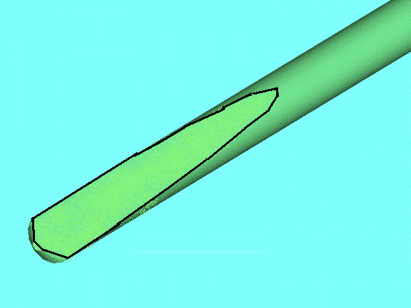

Proposed Pit Design

The 3D rendered model is a result of a best guess of the construction based on discussion within the group working on the module. We summarize that the 4 bolts were used to fix a 12'' x 8'' timber [refer Rabbit Trap Gangway] with the rail supported across the opening by a Universal Beam [U.B.]   A 18'' deep beam fits between the underside of the rail. Standard NSWGR rabbit fencing would have been installed along the right of way and short wings installed on the road side to the rails for that purpose.

The use of the series of undercuts in the top side of the wall still made no structural sense until as a group the concept of a trap was full embraced.

A rabbits road to destruction

History
The question of the reasoning behind these installations is now history but was recently answered by Paul Baker from his conversation with old railway hand at the Arimdale Rail Museum. He explained that the farmer's were required to control rabbits on their property's by the Pastoral Protection Board but the NSWGR was exempt. In time the farmers prevailed on their property's so the rabbits moved to the railway right of way. Here they were safe as the farmer could not enter and the railway were not interested. Two events combined to create a sense of urgency for the NSWGR. The first was the rabbits began to borough in the road base which ultimately lead to collapses and secondly farmers decided to group together and to sue the railways for the damage from their rabbits on their  land. 

The NSWGR found the solution in the using a combination of rabbit proof fences and traps. This allowed the rabbits to be eradicated along the right of way by destroying their boroughs while the fences prevented escape onto the land at either side. The rabbit trap seal the end and provided the final point for extermination. 

Rabbit trap or Modeling trap
In the illustration above shows two possible paths to destruction for rabbits. The trap is mirrored about the track center and repeated on the opposite side with the wall and cast in trenches forming a maize. Any rabbit approaching along the outside of the rail would come up against the 12'' high wall but is presented with a small drop and path down - this would match the rabbits natural instinct to enter borough so it follows the trench along the face of the wall to be presented with another small drop between the end of the wall and the face of the U.B. [not shown for clarity]. Again the rabbit follows the path that worked before and is now faced with a 40'' drop into a pit with no exit and as rabbit cannot turn or back up easily it is trapped with few options,

The center follows the same logic but is much shorter and direct but has the same result for the rabbit. The trenches also would have promoted water to fill the pit in wet periods further increasing deadly nature of the trap.


Rabbit Stop at Yard exit -Spicers Creek

This Rabbit Trap is found on the Spicers Creek side and marks the location of the Spicers Creek Station exit in an embankment. The rabbit trap shown above is located at the yard exit at Spicers Creek and are shown on the plans for the Spicers Creek Yard that Chris Wangmann has as part of his research on the line. The conclusions are supported by plans found for a shunters gangway for rabbits traps [NSWGR Plan #F1846] recently found by Ray Pilgrim and now in the data section of the blog.

Culvert located between Spicers and Drill Creek


This detail is the same as the rabbit trap design but without the wall and channel but suggests that the rabbit trap design is a modification of this standard culvert.

Friday 20 September 2013

MFX's Deck Girders

Deck Girder Construction and Modifications.
The 24' Deck Girders Bridges are manufactured by Waratah Models using all etch brass construction making them ideal to integrate MFxs. The notes below cover some tips for assembly and the modifications to integrate the MFxs


Parts were separated from the frets using a pair of 100 mm pair of stainless steel scissors. These are excellent for trimming off the fine attachment that bind the parts into the fret. They however only last 3 or 4 kits before loosing the edge so purchase a few as they are cheap.

The girders will require a timber jig to solder the top and bottom flanges in there correct relationship to the web. The jigs packers were laminated from 0.5 mm scale lumber to center the flange on the web. The assembly was soldered using 0.5 mm rosin cored electrical solder and paste flux using a temperature controlled iron set at 400 deg C with a chisel tip. Check that the web is located about the flange center-line before soldering the rivet strips.


Timber Jig with flanges installed - Finished girder above

The construction of the kit was altered by removing the internal cross bracing and replacing it with a folded brass channel 45 mm wide x 5 mm high x 0.4 mm thick x 150 mm long.

Tip: When folding metal you gain a gauge at each fold line [material thickness]-to obtain a finished width of 45 mm two metal thickness are deducted to locate the fold lines. The girder sides a packed with tissue paper saturated with water and applied to absorb the heat required to fit the channel.

The top side of the channels supported in its correct position using to strips of 5 mm square lumber - this dimension is not critical. Low temperature [280 deg C] solder is applied at three points along the flange of the channel with heat applied using a propane torch. Start at one end and allow the assembly to cool and move to the opposite end - repeat at the center.

Clean check alignment and repeat for the opposite side

Details

All etches for vertical angles are folded using a "Hold and Fold" from the Small Shop as hand folding proved impractical. After folding the vertical flange there is a notch formed at the end of the angle to fit over the rivet strip located at the base of the flanges. If it is not correctly formed remove a metal thickness at both ends - see photo below. 

Fit to the instructions provided by the manufacturer and solder using 0.5 mm rosin core solder and a propane torch.


Solder located against vertical ready for soldering
Only the front verticals were installed to allow the channel spreader to be fitted

Tip: Apply the heat gently to melt the flux and then move in closer to quickly to build temperature at the center and melt the solder. The heat is initially applied at the center of the vertical on the opposite side to the solder and when at the solder appear to distort move the flame to the other side. Repeat for each verticals allowing most of the heat to dissipate between applications.

The angle spreaders and associated bracing are installed across the girders top and bottom.

SoundFxs
The sound effects are created by a ModelFXs Sound-Byte Player with the bridge rumble file using a exciter speaker mounted about the bridge bent spreader centers.

The exciter speakers were purchased from Parts Express and fixed to the inside face of the channel using the self adhesive mounting pad. A exciter's frequency response and sensitivity are completely dependent on the exciter's designated surface. Thinner, smaller materials will tend to be louder and facilitate mid/tweeter response. Thicker, larger materials will be slightly quieter but result in a more full-range sound.


HiWave HIAX 19C01- 8 19 mm Metal Cup Exciter Specifications:Power handling: 3 watts RMS •Nominal impedance: 8 ohms • Mounting diameter at face: 22 mmBody diameter 40 mm(including terminals) x 13 mm H • Weight: 29 grams.


The ModelFXs Bridge sound file is as dimensionless [speed] as practical but still creates a fixed relationship to equipment crossing the bridge so a fixed speed restriction will be applied in that area of the layout.

Sound and Control Logic Overview
The player plays the sound on continuous loop with one of the speaker wired run through the normally open contact of a NCE Dual Relay. A BOD20 detects the presence of a train and triggers an output on a NCE Mini Panel with code associated with that output triggering an output on a NCE Switch 8 stationary decoder activating the coil on the Dual Relay connecting the speaker. This approach combined into the three bents using the same logic allows the sound to effectively follow a locomotive across each bents.

Air Movement
To create a sense of motion the air movement associated with trains crossing a bridge is to be simulated with a fan. The fan is used to push away mist at the base of the bridge which is created with a ultrasonic mist generators. These will be employed during the night to fill the creek bed with water mist for the early morning trains to run through.


Ultrasonic Mist Fogger 24v DC


Two axial 5V DC fan are fitted at the entrance's of the center bent and are coordinated by the locomotive using a pair of BOD20's located on the opposite rail to the sound triggers. The fans are mounted between the girders pointed too the creek bed and are controlled using two NCE D13SRJ functions with the firebox flicker effect assigned to the function to flicker the fan creating flukey air movement of the real world. The D13SRJ decoder are controlled by the code in a NCE Mini Panel associated with the triggering BOD20.

Fan 5v DC - 20 x 20 x 10 mm

Control Logic Overview
All electronics will be located in the module drawers fitted to the base of the module frames. This will allows repair and diagnostics to be achieved without removing models and electronic hardware from the layout. Full schematic and control logic will be found in the article on Spicers Creek Control Logic

Wrap up
MFxs cannot replicate real life as scaling effects are difficult to overcome but MFxs is an attempt to suspended the reality of a viewer and if that is achieved the goal has been achieved. Only time will tell if the result is success but for this builder simulation is the next frontier in all our hobbies involving modeling and motion and there has never been a better time to try.

Wednesday 4 September 2013

Track Laying

Curved Track
Curved rail is prepared in advance as per the straight rail except it is curved to radius to fit its location. Preparing curved track work is not very different than building straight track work and does not require any special skills. The real difference is that the rail's needs to be curved. To ensure that the rail is properly pre-bent into shape consider purchasing a Fast Tracks Rail Roller.


The Fast Track Rail Roller tool will not only make it easy to create smooth consistent curves, but will also ensure that the rail is properly pre-bent so that it will retain its shape over time. For curves use  track gauges to ensure smooth curved track work and is especially important at joints between individual sleeper bases.

Failure to properly pre-bend the rail for curved track work will result in failure over time! 

Track Laying General.
After preparing the road base and ensuring it is 100% flat the time has come to install the track work. What will be outlined here is the basic technique applied to that task. 

The golden rule is bad track work CANNOT be fixed...!

Curved Rail ready for Installation
The base as shown was fixed using acrylic sealant to the layout road base following the drawn center line and once the primer is dried the rail is inserted onto the tie plates in 840 mm length [ 40 feet x 3]. Each piece of rail is prepared for metal rail joiners at both ends and the plastic 6 bolt rail joiners are applied at  40 scale feet as described in the  the Turnout article.


Drilling Tie Plates for Spikes
The choice of the Peco Track Pins is described in the article on Turnouts which worked with no real issues so when problems occurred when spiking the rail it was a shock and required a rethink. The problem lied with the laser cut ply bases that the sleepers are attached to combined with the weakness of the pins. The pins fold up trying to be pushed through the ply base. 

Initially 0.020' [0.5 mm] drill was used but the pins just slipped into holes with little apparent holding power. The real issue was the short life and cost so another way had to be found. The answer was found in spring wire 0.020'' [0.5 mm] which was filed into a simple D bit by grinding 5 degree taper then form a point at the end. Using a small battery drill and chuck the wire drill cleanly through the sugar pine sleeper and ply base. In most cases the pins press in with a slight pressure were the pins fold up re-drill till success is achieved. These drills will bend to unbelievable angles without breaking and a length of piano wire will supply as many as any project would need. Another advantage is that the hole created appears to close up after the pin is inserted and develops excellent holding power.


D-BIT


Another problem was found with the foam base - it dose not resist pressure well but it was found that a scale ruler spreads the load enough to overcome this problem. To make this task easier adhesive was not applied at at the edges of the sleeper base.

Electrical Connection

Each rail is connected to the bus with 0.5 mm multi-core wire soldered to a brass tabs which in turn is soldered to the base of the rail . Even though the rail joiners are brass castings you do not depend on them to transmit DCC signal that the job of the wire.

Spiking Rail

When spiking it is critical that when the spike is inserted that it follow the path of the drilled hole. The shape point is necessary to successfully insert the pin but it will generate its own path and will fold the pin. 


In practice it has been found that the head of the pin should be bent from the normal axis to obtain a tighter fit. This is best done by drilling the hole at 5 degrees to the vertical. The pin is inserted until the spike pliers strikes the rail flange - using the pliers bend the head into the vertical and complete the insertion of the spike to the flange base


The Final Result

At this point the track is ready for weathering and ballasting which will be covered in separate articles.

Is there a downside its the speed but a looking at the finished product you are reminded it is all worth while - I think...!