Sunday, 15 June 2014

Spicers Creek Station

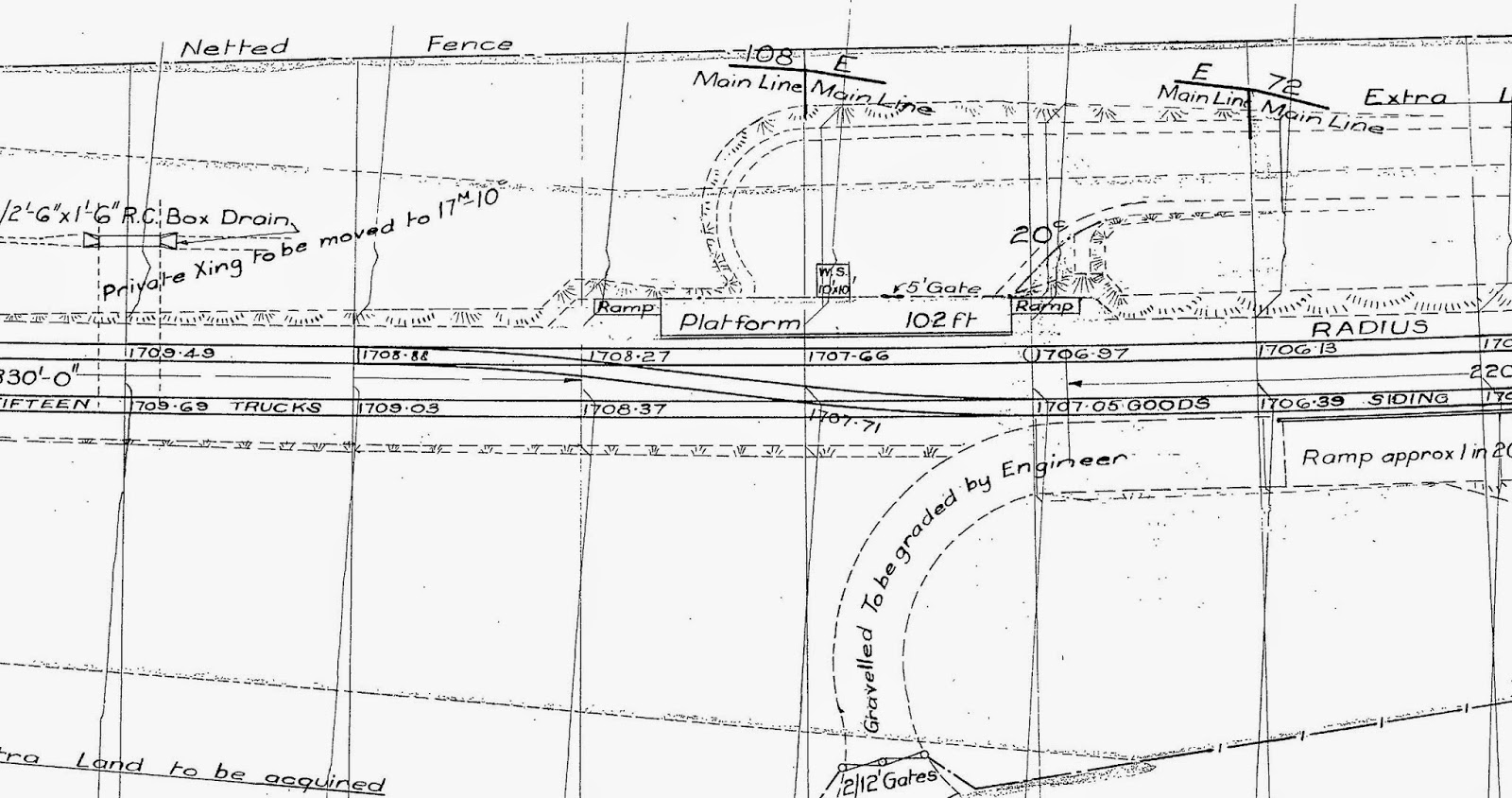
Though I will not be modelling Spicers Creek Station any new information will not be rejected. At the Epping Show with the two modules on display, I was offered some plans for the complete Spicers Creek Station. The actual plan received is so large it is not practical to reproduce it here so two critical sections have been extracted.


Spicers Creek Station


Gulgong Side Yard

The most important piece of information is the reference to "Netted Fence" - it is confirmed that both side's of the line would have been fitted with rabbit-proof fencing.

Put simply it means that the whole model will have to have mesh fence constructed if the original date of construction in the mid 30's is to be used as a starting point..!

Thursday, 6 March 2014

Convention 2014

I would like to take this time to thank every one who assisted in the operation of modules at the convention. A special thanks to Geoff and Ben Small for their personal advice and assistance.

The modules will have their final public show at the Epping Model RR Club Exhibition in June of this year.

Video by John Parker - Click here

The photos were taken by Ray Pilgrim


Thursday, 30 January 2014

Crane Gantry Model

The NSWGR Gantry Crane was found on many sidings within the system. The model was produced from the data sheet provided by Greg Edwards detail using photos of the prototype located Merriwa. Additional detail photographs were sourced from Kerian Ryan Models showing a crane at Ardlethan from his range of Australian Railway Detail Photographs. The completed model is all brass, assembled, painted ready for installation and available in HO and O scale.

Features:
  • All brass & painted ready to install [Footing is painted in a concrete colour]
  • Chain blacken brass 40 links [HO] & 27 links to the inch [O]
  • Wire is 0.008'' elastic line
  • Available in HO [1:87] and O [1:43.5] scale
  • Developed by ModelFXs.com
The sidings diagrams for Drill Creek and Goolma showed a crane and are marked as 5T. The diagrams are in the research chapter - for information Click Here

          Available exclusively from  from Model RR Craftsman - CLICK HERE


Saturday, 25 January 2014

Track Base Post Script

The reduction of sound produced by the layout track base itself has been a prime objective and the process outlined in the Track Base article worked when reviewed by others at the state shown in the article and below. 

When the foam blocks used in the scenery were glued on both sides it was a different case. The noise of a piece of rolling stock was overpowering and something had changed. The open area under the road base was sealed by the scenery foam on two sides and the urethane foam base - a drum had been created. 


As sound requires air movement the best way to stop unwanted sound is to stop the movement but with what?

Cut using a fine wood saw

Stuffing the gap

The solution was found in using foam as it easily compressed to fill the cavity. Clarke Rubber stocks a 100 mm [4''] foam mattress and for a extra $10 it was cut into 150 mm [6''] strips. These are pushed into the cavity before the last scenery foam block is installed - problem solved. In any future construction this foam would be installed as part of the road base installation. The off-cuts have been used to seal the smoke ducts, gaps in the scenery and as a signal base.

Wednesday, 22 January 2014

Scenery Base

The scenery base used is styrene foam from Australian Urethane & Styrene 150 mm thick. The foam is called MGDE by the supplier and was purchased in 1200 x 600 x 150 blocks and was selected as it is carve-able and is used for stage set manufacture. The use of 150 mm allows the scenery to be carved without encountering layers of glue required for laminates. The foam was fixed to the urethane foam deck using large dollops of Parfix Gap Sealer applied to the urethane foam deck [pale yellow in photo]


It was planned to hot wire the styrene foam block but after expending time and money this was abandoned. The final solution for the cutting lay in a oscillating saw as it allows clean cuts with little dust unlike using a saw. 
Oscillating Saw

The technique used with the short circular blade is run to full depth along a desired cut line and then cut from the top cut down to intersect and just lift out the waste wedge. The second technique is to cut the desired line then using the saw to lever out chunks both techniques were used as required. 

Foam V cut into exiting scenery

Once the rough cuts are completed the saw can then be used to remove and shape roads and other areas by just flying over the surface removing wafer thin pieces. It is quick and produces very little dust but is noisy - wear hearing plugs. A small hand saw and box cutter blade were used also as required.

Applying base.
The foam appearance was removed by selecting a suitable latex house paint from Brinlay Paints. A beige colour from their standard colour card was selected as the base colour. Prepare the paint by thinning, remove approximately 15% of the paint and place aside for later use. Thin using a squirt of liquid detergent and methylated spirits and water about 50/50. Thin till the paint runs gently off a stick in defined drops, add paint back if required - stir well before use


The base is formed by using Kleenex Cottonelle toilet paper and a cheap stiff brush. Paint an area of foam with the paint, then apply leaves of the Cottonelle in a random pattern - do not be afraid to overlay - do not quilt the paper.  In the photo they are shown in a line, this was due to the confined area to be repaired. Breaking the rule only proves there is a rule.


Stippling the paint

Dip the brush back into the paint to grab a small amount of paint onto the tip. Using a stippling action work the paint onto the foam and paper till they combine. If you tear or lift up a piece of paper just apply another leaf across the effected area and repeat. Continue to use the stippling action to spread the paint till a Matt finish is achieved.


Finish area

What is achieved is a earth like texture and removes the bead look of foam. This technique comes into it own when modifications are required as it tidy and precise when working around finished scenery.

The End Goal

Looking down the road to Spicers Creek Station

Aerial view of road to Spicers Creek Station

Sunday, 19 January 2014

Modules Post Script

Now that the Spicers Creek modules are assembled it's time to report on what worked and what didn't. Overall the finished result met the design criteria laid out in the original construction article but like all designs there is room for improvement on the original concept. The  original article has now been updated to reflect these changes.


Structural Elements
In this respect the combined elements are strong enough but each module must be fully assembled as there are no redundant components and each fulfills a specific roll in the structure of the module. The module should be assembled on a relatively flat surface as it will move on all axis's until all the parts are installed.

The design can be seen as two separate elements of a base board and the backdrop / roof. These base is formed by the lower leg of the former's which are located by installation of the stringers. A ply deck is fitted at the bottom with 2400 x 600 x 25 urethane fitted to the top side, these prevent lateral movement while the front and rear fascias provide the load carrying beams for the structure. The lower deck is cut out to allow access to the structure for wiring the layout while the upper deck provides the mounting face for the 600 x 1220 x 150 foam scenery blocks. The combination of the decks and stringers provide  the  torsional [twisting] resistance required by a base deck. 


The skeleton of former's is placed temporally on two 90 x 40 x 3800  runners clamped to on two saw horses. Align the deck former's by fitting the stringers, fit the upper an lower decks to the former's  and allow adhesives to dry.  Finally fit the front and rear fascias - again glued and screwed to the stringers holding the former's in position. The track base can be added now or later in the process but cutouts for the risers must be provided in the top deck.


These were cut using a Muli-function Oscillating Power Tool with a series of plunge cuts which was later was used in the shaping the scenery foam.


The styrene sheet provides the lateral stiffing for the roof former's while filling in the big gaps to create the backdrop. This was done by placing the rear of the assembly on a floor, leveling and squaring it and once all is square then fixing the styrene sheet using liquid nails. 

Extractor Duct
A smoke extractor duct is fitted for the full length with a fan fitted at each bay. This duct will be drilled as required latter to extract oil smoke should they be installed. It also allow the running of two [2] 25 mm quads which the NCE lighting is fitted to and this will be covered in a separate article. It would be better if the duct was flush with the roof as when the LED's were trilled it was found that a single row is capable of lighting the whole module. This is covered in the article on the NCE LED lighting.

The foam is bonded to the top side of the fascia using Parfix No Gaps. The foam block should be glued to the deck  leaving a 5 - 6 mm gap to the back side of the fascia. This gap is filled with the Parfix to structurally bond the two and at the top side provide a joint that will not crack over time.


Issues
The former's do need a 40 or 50 mm  x 3 mm ply glued to there faces for the styrene to be fitted too as the 12 mm former;'s provide a narrow gluing face for the styrene which tended to hog the plastic around the rib. A wider face should resist that while providing a larger attachment for the styrene that would be less critical at assembly. The styrene should be fitted in one piece from the base to the roof fascia to create vertical joints only. On the Spicers creek module it was laid along the frame creating  vertical and horizontal joints to create just more work.

Modules should be designed in 1200 increments as the styrene is supplied in nominal 1220 wide sheets so you could use 1223 - 1224 spacing to avoid cutting. The styrene sheet should be increased to 2 mm or the ribs closed up to 460 mm from the 600 used on the Spicers Creek Module

Leave gaps between sheets of about 3 mm this makes for a stronger joint. Joints were sanded with a orbital sander and 80 grit paper. All gaps were filled using Parfix Gap Filler. This is applied with a 200 wide blade dipped in water to obtain the smoothest possible joint and the edges wiped with a damp sponge to feather them in. If you allow to to dry for 48 hours and sand gently the orbital sander can be used..


All joints should be joined using a scrap timber along the full length of the joint to ensure a clean joint ant the stringers and former's. This backing piece should be covered on the glue side with the brown packing tape to provide a glue release. During construction it was discovered that the best solvent [adhesive] is lacquer thinners for the HIPS plastic. Just apply with a brush along the seam and capillary action completes the tack. This is the only effective jointing method that has been found and also allow repairs using a backing piece for any cracks.

Handling


Each module is fitted with 65 mm o.d. swivel wheels so when they are moved you simply push the module into the venue extend the legs, add power and operate. These are a must with each module being 1350 wide  x 1250 high x 3800 long and weighing 80 kg. This makes the movement a simple task for one man.


Legs
Each module is fitted with 4 commercial folding legs. These simply extend two at each end to support the module. Two are required at each end to provide the necessary stability due to the modules width.


Drawers
These are a must have item and this will be fitted with all the control and sound cards plus other electronics. This are a must have for access to the control electronics or just for storing stuff. The drawer was constructed using commercial soft close runner kits.


A 40 x 20 x 1.5 aluminium angle is run under the lower stringer and screwed and glued using structural adhesive such as liquid nail's to providing a  mechanical tie and edge protector under the cutout for the drawer. Screw to all former's and both sides of the draw to exploit the load capacity of the aluminium. If drawers are not fitted a 20 x 20 x 1.5 will provide a edge protector.


Lettering
Vinyl Lettering offer a convenient and easy to follow on-line service for those who need lettering in a hurry. White self adhesive were ordered for Spicers Creek, Goombla Road, Module Name, Sponsor and blog address.

Conclusion

Did it all work - well, yes. The assembly is strong, dose not twist and is awkward to handle but with the integrated handling hardware it is manageable by two people.
Would I do it another way - no it meets my needs!

Each of the major points on the Spicers Creek module were identified for the benefit of the viewers. This allows people to put a name to the scenes we chose to model but keep to ourselves.

Would anyone duplicate these modules, it is doubtful as they were designed to fill a very specific need but there are elements of the design that may be useful in the design of other modules. 


This is why we all do this work......!


Crossing to Spicers Creek Station